Prod Technique (Current Flow Prods - CFP)
With this technique the current is introduced into the item under test by using electrical contacts known as prods. Prods induce a distorted circular magnetic field within the specimen using current values typically in the region of 1000 amps; at this current level arcing can occur between the electrodes and the test surface causing damage. Arc strikes cause localised hard spots on high carbon or high carbon equivalent steels which may result in micro cracking. To prevent this possible damage, the prod contact tips and the test surface must be kept clear of any contamination and the current must not be switched on until firm contact has been established. Likewise, the current should be switched off before lifting the prods. Because of the risk of arc strikes, many specifications do not allow the use of the prod technique.
Precautions when using current flow in respect to prods/clamps shall be taken to prevent excessive heating, burning or arcing. Certain metals including copper and zinc (including galvanised prod tips) may, if used as prod material, contaminate and cause metallurgical damage to the component if arcing occurs. For this reason, and the fact that perfect contact is difficult to achieve with prods, ideally they shall be made of steel or aluminium. Zinc shall not be used. Copper or copper-tipped prods shall be used only in applications where complete assurance can be given that metallurgical damage will not occur. The cleanliness of both prod contact faces and the component shall be such to ensure good electrical contact. Prods shall have a minimum dimension of 10 mm and shall have as large a contact area as possible. Arcing or excessive heating shall be regarded as a discontinuity requiring a verdict of acceptability. If further testing is required on such affected areas, it shall be carried out using a different technique.
Note:
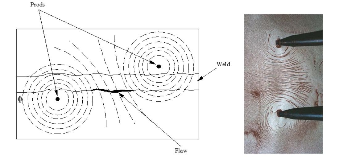
- Aluminium or copper contact pads/tips are often used due to being a good conductor of electricity. Since the lines of force radiate from prods, correct positioning is essential to ensure that all possible discontinuities are located. Ideally the prods should be in a line parallel to, and on the same axis, as the discontinuities being sought.
BS EN ISO 9934-1 quotes two formulas for prods depending on the required area of inspection, i.e.:
I = 2.5H x d; for a rectangular inspection area
I = 3H x d for a circular inspection area
Where:
I = amps A.C. r.m.s.
d = prod spacing in mm’s
H = tangential field strength in kA/m
When using prods the field strength and direction should normally be checked by the use of flux indicators.
Advantages of the prod technique include:
- A.C. or D.C. fields.
- A.C. energised equipment may be used for demagnetisation operations.
- Low voltage output. No poles to attract magnetic particles. -Variable field strength, on/off control.
- Can be used in confined spaces.
- Relatively fast coverage of area under test.
Disadvantages include:
-
Risk of creating arc strikes (forming localised hard spots which may contain cracking).
-
Heavy transformer required.
-
Classed as a two person operation (due to one person holding the prods and one person applying the magnetic ink or powder).
-
Contacts and small test items can overheat.
-
Careful positioning and spacing of prods required.
-
Possible to switch on without creating a field. A good contact is required. If the required magnetism is not being achieved, it may be necessary to re-clean the test surface or file the prod tips
-
May leave residual field which interfere with next prod positions. When dealing with residual magnetism in compounds, the most objective is a circular field, since it is contained in the material making it difficult to detect and/or remove
-
Expensive equipment.